FlashPro5 Device Programmer Quickstart Card
This quickstart card applies only to the FlashPro5 device programmer.
Kit Contents
| Quantity | Description |
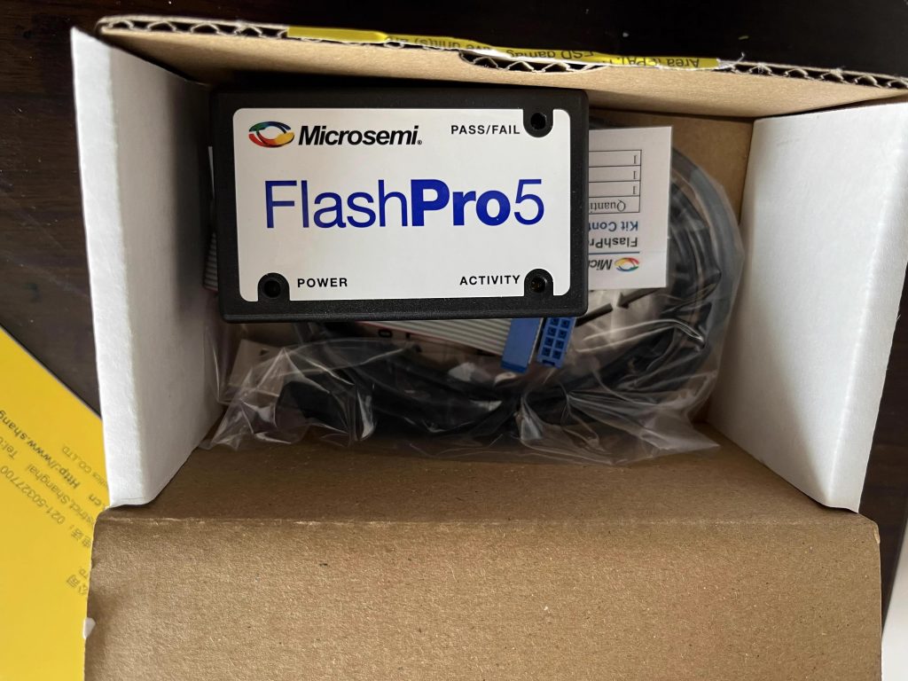
| 1 | FlashPro5 programmer standalone unit |
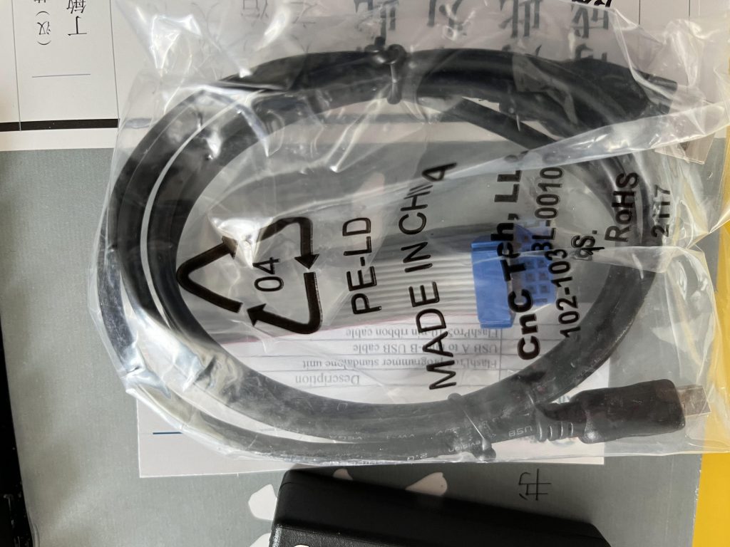
| 1 | USB A to mini-B USB cable |
| 1 | FlashPro5 10-pin ribbon cable |
Software Installation
FlashPro or FlashPro Express software is automatically installed as part of the Libero? System-on-Chip (SoC) software. If you are using the FlashPro5 device programmer for standalone programming or on a dedicated machine,
download and install the latest release of the FlashPro or FlashPro Express from the Microsemi? website. The installation will guide you through the setup. Complete the software installation before connecting the FlashPro5
device programmer to your PC.
Note: The minimum version requirements to run FlashPro5 on Windows are Libero SoC v11.3/ FlashPro v11.3 and on Linux are Libero SoC v 11.4/ FlashPro v11.4:
www.microsemi.com/products/fpga-soc/design-resources/programming/flashpro
Hardware Installation
After installing the software successfully, connect one end of the USB cable to the FlashPro5 device programmer and the other end to your PC’s USB port. The Found Hardware Wizard will open twice. Use the wizard to install the driver automatically (recommended). If the Found Hardware Wizard cannot find the drivers automatically, then ensure you h*e properly installed the FlashPro software prior to installing the hardware. If the drivers still cannot be installed automatically, then install them from a list or specific location (advanced).
If FlashPro was installed as part of the Libero SoC default installation, the drivers are located at C:/Libero/Designer/Drivers/Manual. For a standalone Libero SoC FlashPro default installation, the drivers are located at C:/Microsemi/FlashPro_<ver>/Drivers/. Microsemi recommends the automatic driver installation.
Note: FlashPro5 uses pin 4 of the JTAG connector whereas FlashPro3 had no connection to this pin. FlashPro5 pin 4 of the JTAG header is a PROG_MODE output drive signal. PROG_MODE toggles between programming and normal operation. The PROG_ MODE signal is intended to drive an N or P Channel MOSFET to co*ol the output of a voltage regulator between the programming voltage of 1.5 V and normal operation voltage of 1.2 V. This is required for ProASIC?3L, IGLOO? V2, and IGLOO PLUS V2 devices because, although they can operate at 1.2 V, they must be programmed with a VCC core voltage of 1.5 V.
Figure 1 ? Pin Assignments
Pin 4 on FlashPro5 programmers MUST NOT be connected or used for anything other than its intended pur*e.
| July 201 |
If the On LED does not light up after FlashPro5 driver installation, the driver might not be installed correctly and you must troubleshoot the installation. For more information, refer to the FlashPro Software and Hardware Installation Guide and the “Known Issues and Workarounds” section of the FlashPro software release notes: www.microsemi.com/products/fpga-soc/design-resources/programming/flashpro.
FlashPro5 may not operate correctly if pin 4 of the JTAG connector is improperly used.
Documentation Resources
Refer to the FlashPro software page for further information:
www.microsemi.com/products/fpga-soc/design-resources/programming/flashpro
Technical Support and Contacts
Technical support is *ailable online and by email.To find your local representative visit Microsemi SoC Sales offices, including Representatives and Distributors which are located worldwide.
CE (European Conformance)
This product complies with the requirements specified in EMC Directive 2004/108/IEC and RoHS Directive 2011/65/EU.